Non-Destructive Digging for Solar and Renewable Energy Projects

engineering-grade documentation

Solar and renewable energy construction involves trenching for collection lines, installing foundations and equipment pads, building access roads, and connecting to existing electrical infrastructure. Every one of those activities intersects with buried utilities. Non-destructive digging methods, including vacuum excavation, private utility locating, ground-penetrating radar, and utility potholing, give project teams physical confirmation of subsurface conditions before mechanical excavation begins. The cost of striking an unknown water line, gas pipe, fiber-optic cable, or electrical conduit reaches well past the repair invoice, since project delays, safety incidents, regulatory penalties, and strained utility-owner relationships all follow.

Below, you will find how each method works, the risks specific to solar and battery storage sites, when vacuum excavation earns its cost, how utility mapping supports construction and long-term operations, and what to look for in a provider. We also break down the damage prevention sequence, from record review and 811 notification through private locating, targeted potholing, and final documentation.


Key Takeaways

  • Non-destructive digging confirms utility location and depth before high-risk excavation, reducing reliance on incomplete site records
  • Solar and renewable sites often contain public, private, abandoned, or poorly mapped utilities that 811 services may not fully cover
  • A layered workflow combines 811 calls, private utility locating, GPR scanning, vacuum excavation, and utility mapping
  • Controlled physical exposure and documentation reduce safety incidents, schedule delays, repair costs, and project redesigns
  • Providers should be evaluated on service integration, field documentation quality, limitation transparency, and renewable-site coordination experience

Non-Destructive Digging Methods Used on Renewable Energy Sites

Defining Non-Destructive Digging Techniques

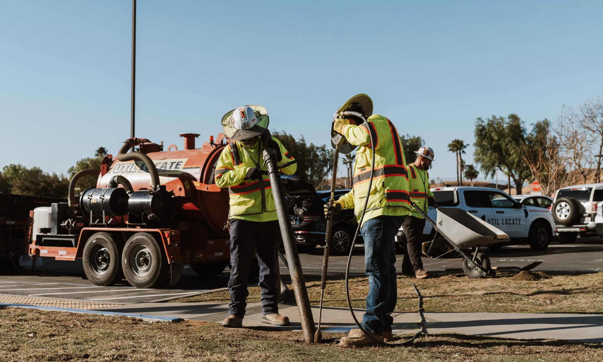
Non-destructive digging covers methods that expose or identify underground utilities without mechanical damage. Vacuum excavation, also called utility potholing, uses high-pressure air or water with suction to remove soil and verify the depth, size, and material of a buried line before heavy equipment enters the work zone.

Ground-penetrating radar scans subsurface layers with electromagnetic pulses to identify non-metallic pipe, fiber, rebar, post-tension cable, and voids without breaking the surface. Calling 811 triggers the free national before-you-dig service, which has public utility owners mark registered infrastructure. Private locating covers facility-owned lines, abandoned utilities, and anything missing from public databases.

Method What It Detects Typical Renewable Site Use Known Limitation
Electromagnetic locating Metallic pipe, steel gas line, copper communications, energized conduit Initial sweep of trench routes, pads, and tie-ins Needs a conductive path and signal access
Ground-penetrating radar PVC and HDPE pipe, fiber, vaults, rebar, post-tension cable, voids Suspected corridors and pads before cutting or coring Varies with soil moisture, clay, and depth
Vacuum excavation Exact depth, diameter, material, and alignment Crossings where trenches meet duct banks or mains Confirms only the points that are dug
Utility mapping Permanent record of location, depth, type, and owner As-built documentation for turnover and O&M Reflects conditions at time of survey

Key Benefits for Solar and Renewable Construction

Buried-utility damages cost the United States roughly $30 billion each year, which frames the exposure renewable projects carry when excavation planning rests on incomplete information. At the end of 2024, more than 280,000 U.S. employees spent most of their time on solar projects or manufacturing work, with another 90,000 spending less than half their time on solar work.

Another 79,000 jobs supported battery energy storage systems in 2024, a 4 percent increase year over year. That workforce operates where trenching, boring, foundation work, and pad construction create daily chances for utility conflict, which puts damage prevention at the center of planning for EPCs, developers, civil contractors, and facility managers.

Differences Between Non-Destructive and Traditional Excavation

Vacuum excavation confirms utilities at specific conflict points, while mechanical digging proceeds without visual verification. Non-destructive digging is a targeted method, not a replacement for every excavation task across a solar array or wind farm.

While vacuum excavation costs more upfront than mechanical digging, it lowers total project risk by removing unverified excavation near suspected corridors and the later costs of repairs, rework, outages, and change orders. Open excavation also complicates spoil handling and increases liability when a utility is struck.

Non-Destructive Digging Addresses Underground Risks on Solar Sites

Hidden Public and Private Utility Conflicts

Solar and renewable sites routinely contain electrical lines, communications cable, water mains, gas pipe, irrigation systems, fiber, and conduit from earlier construction. Former farmland retains irrigation lines and drainage tile, while industrial, municipal, and campus parcels hold power distribution, storm drains, sewers, and abandoned utilities that were never formally decommissioned.

Private utilities owned by the facility operator, developer, or previous landowner sit outside public records and go unmarked during a standard 811 request. Private locating is what identifies those facility-owned and unrecorded lines, which professional potholing services then confirm before excavation proceeds. Prior land use is the fastest predictor of what a crew will hit.

Prior Site Use Commonly Buried Infrastructure Verification Priority
Agricultural land Irrigation mains, drainage tile, well lines, farm power drops GPR sweep, pothole at crossings
Former industrial site Process piping, power distribution, tanks, storm drains Full private locate before trenching
Campus or municipal Duct banks, steam and chilled water, sewers, fiber Pothole every tie-in point
Commercial parking lot Lighting circuits, storm lines, fire service, conduit runs Concrete scan, pothole at pads
Undeveloped parcel Transmission crossings, pipeline easements, unrecorded services Record review, 811, GPR on roads

Safety, Schedule, and Financial Implications of Utility Strikes

That $30 billion estimate covers more than repair invoices. It carries emergency shutdowns, rework of finished trenching, redesign of collection routes, and timelines that trigger liquidated damages or push interconnection milestones. More than 350,000 service interruptions occur each year from utility strikes across all construction sectors, each carrying potential for worker injury, public safety hazards, and enforcement action when high-pressure gas or energized lines are involved.

Striking a utility during array trenching can halt an entire site while repairs run, leaving crews idle and pushing commissioning into a later interconnection queue window. Redesign and change orders after a conflict multiply costs well beyond the repair, especially when pads, inverter locations, or collection routes have to move.

Challenges of Stale As-Builts and Unrecorded Infrastructure

Stale as-builts create wrong assumptions about depth, alignment, and abandoned lines that were never documented at decommissioning. Incomplete maps, common on repurposed industrial sites, former campuses, and farmland, offer little guidance when ground-penetrating radar uncovers subsurface features that appear on no available drawing.

Old drawings omit temporary utilities that became permanent, miss field changes, or show planned routes instead of installed ones. Skipping the 811 call remains the single largest driver of damage to buried utilities, and even with 811 filed, unrecorded infrastructure still carries risk.

Utility Locating and GPR Support Safe Renewable Excavation

The Role of Electromagnetic Utility Locating

Electromagnetic locating detects conductive utilities such as metallic water pipe, copper communication cable, steel gas line, and energized conduit by tracing signals they carry or that a transmitter induces. It needs a conductive path and an accessible signal point, which makes utility locating services effective for mapped utilities with known access points and less reliable for abandoned lines or non-metallic infrastructure.

Util-Locate reports up to 97 percent accuracy for electromagnetic locating and capability up to 13 feet deep under favorable conditions. These figures are client-provided performance data, and field results depend on soil conductivity, utility material, signal interference, and operator experience.

Ground Penetrating Radar Identifies Non-Metallic Utilities and Voids

GPR complements electromagnetic locating by finding features that carry no current: PVC water and sewer pipe, HDPE conduit, fiber without trace wire, concrete vaults, voids from settlement or erosion, and steel or post-tension cable inside slabs and pads.

GPR performance shifts with soil moisture, clay content, depth, and the material contrast of the target, so results need professional interpretation. A GPR scanning service delivers real-time subsurface imaging that helps renewable project teams decide where physical confirmation through vacuum excavation belongs.

Limitations and Field Guidelines for Combining Locating Methods

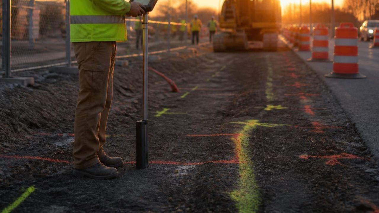
Utility locating identifies probable paths and produces field markings that guide planning. High-risk crossings still need physical confirmation, such as where a collection trench meets a duct bank or where a storage pad will be poured over suspected infrastructure.

Private locating does not replace the legal requirement to contact 811 where state or local rules mandate notification. A sound field approach combines 811 compliance, private electromagnetic and GPR locating where facility-owned or unrecorded utilities are suspected, and targeted vacuum excavation at critical conflict zones.

Vacuum Excavation and Utility Potholing Confirm Buried Utilities

Situations That Require Physical Utility Confirmation

Vacuum excavation and potholing belong on the schedule when plans show construction crossing existing utility corridors, when as-builts are incomplete, and when locating or GPR reveals anomalies that need physical exposure.

Collection routes that cross access roads, duct banks, or irrigation mains need verification before trenchers work those zones. Storage pads, transformer foundations, switchgear, and interconnection equipment sit in congested space near existing tie-ins, where accurate depth and clearance come only from controlled exposure.

Advantages of Vacuum Excavation Over Mechanical Digging

Vacuum excavation removes soil with suction rather than mechanical force, so operators expose utilities without cutting, crushing, or abrading pipe walls, cable jackets, or conduit. Controlled exposure allows inspection of depth, diameter, material condition, and alignment before bulk earthmoving starts nearby.

Targeted potholing costs more per linear foot than continuous trenching, and it prevents the far higher costs of repairs, outages, route redesign, and third-party damage claims when excavation hazards and utility strikes follow unverified digging.

Typical Renewable Project Touchpoints for Potholing

Collection lines connecting inverter strings to the substation run thousands of linear feet, where a single low-probability conflict causes real delay. Commercial, municipal, healthcare, school, airport, and industrial campuses adding arrays, EV charging, or microgrid infrastructure sit over utility networks built across decades, which makes utility potholing highly recommended for construction projects in those settings. The table below maps common work areas to the verification each one calls for.

Project Area Excavation Activity Recommended Verification
Collection line trenching Open trench and plowing across long runs Locate the route, pothole crossings
Storage and transformer pads Mass excavation and foundation work Locate, GPR, pothole the footprint
Access roads and drainage Grading, culverts, stormwater structures Locate before grading, pothole culverts
Substation tie-in Excavation near energized duct banks Pothole every crossing before digging
O&M and repowering Trenching beside operating arrays Use existing maps, re-verify changes

Utility Mapping Strengthens Renewable Site Planning and O&M

Creating Actionable Utility Maps from Field Data

Utility mapping converts temporary paint marks and handheld GPS points into permanent CAD drawings, GIS datasets, and georeferenced site plans that serve the build and later maintenance, expansion, or repair.

A utility map identifies buried pipes, lines, and cables, and typically includes depth, type, material, owner, and alignment against site benchmarks. Survey-grade GPS and robotic total stations support engineering design, construction layout, and as-built documentation.

Documentation Benefits for Construction and Future Asset Management

Field markings fade, get covered by traffic, or become illegible across a multi-month build. Mapping creates the record that outlasts them and reduces the chance that O&M crews strike a utility during inverter replacement, tracker repair, drainage upgrades, or expansion, protecting the asset value owners expect from a 25- to 35-year operating life. Comprehensive utility mapping also supports turnover by giving incoming O&M providers verified information instead of repeating locating and potholing every time excavation comes up.

Integrating Utility Maps into Project Turnover and Repairs

Turnover packages increasingly include utility maps in final as-built submittals, so operators, maintenance contractors, and future engineering teams work from the same information that guided construction. When repowering replaces aging inverters or electrical gear a decade later, those maps help new contractors avoid lines installed, relocated, or abandoned in earlier phases.

Repairs driven by equipment failure, weather damage, or component replacement benefit from documented locations, which let crews excavate with confidence and cut repeat locating costs.

Damage Prevention Workflow for Renewable Construction Sites

Starting with Records, 811, and Site Review

The workflow starts with a review of site plans, as-builts, one-call responses, survey data, and any utility information held by the site owner or prior contractors. Contacting the state 811 center a few business days before digging prompts member utilities to mark registered infrastructure. Teams supply the property address, county, nearest cross street, project type, and exact excavation area so locators reach the correct work zone.

Combining Locating, GPR, Potholing, and Mapping Steps

After 811 marks are placed, private locating and GPR scanning cover areas where facility-owned, unrecorded, or abandoned utilities may exist. Locators mark probable alignments with paint, flags, or stakes. Vacuum excavation then verifies critical utilities at crossings and excavation limits, and field findings become maps and as-built documentation used through the project life cycle.

Step Action Output
1. Records review Collect plans, as-builts, survey and utility records Suspected utility inventory
2. 811 notification File the ticket days before digging Public utilities marked
3. Private locating and GPR Sweep facility-owned or unrecorded areas Marked alignments, flagged anomalies
4. Vacuum excavation Expose utilities at crossings and corridors Verified depth, size, material
5. Mapping Convert field data to CAD, GIS, as-builts Permanent record for O&M

Prioritizing High-Risk Points and Coordinating with Construction

Effective utility damage prevention concentrates physical confirmation at high-risk points, such as where trenches cross duct banks, where pads sit near known corridors, or where boring pits meet congested zones, rather than potholing every foot of a multi-mile collection system.

Coordination keeps locating, GPR, and potholing ahead of equipment mobilization, so crews hold verified information before digging starts and can adjust routes when a conflict surfaces. Tailgate meetings, marked excavation limits, and direct communication between locators and crews reduce the chance that operators work outside verified zones or read missing surface markings as proof that nothing is buried.

Provider Selection Criteria for Non-Destructive Digging Services

Evaluating Technology and Field Expertise

Project teams should check whether a provider offers integrated subsurface services, meaning locating, GPR, vacuum excavation, and mapping under one contract, or whether several vendors must be coordinated. Providers with renewable field experience know what trenching through former farmland involves, how to work on active commercial campuses, and how to coordinate with utility owners during interconnection.

Util-Locate was founded in 2001 and performs more than 11,000 locates a year for universities, healthcare systems, airports, and utility companies across Southern California and Arizona, which reflects the capacity large renewable projects require.

Clear Communication About Limitations and Risks

Providers should state the limits of each method instead of claiming universal accuracy. Electromagnetic locating depends on conductive utilities and accessible signal sources, GPR performance varies with soil type, moisture, and depth, and vacuum excavation confirms only the points that are dug.

Open discussion of those constraints lets teams put verification budgets where it matters, concentrating confirmation on high-risk zones while accepting reasonable uncertainty where excavation can proceed with caution.

Detailed Documentation and Coordination Experience

Renewable projects benefit from providers who deliver CAD drawings, GPS coordinates, depth measurements, photographs, and written reports that construction managers can fold into project records. Coordination matters most when civil, electrical, and mechanical work runs at once and each subcontractor needs verified information at a different phase.

Providers familiar with renewable schedules know locating and potholing happen in stages as site access opens and work zones shift, which calls for flexible mobilization and communication that matches EPC processes.

Non-Destructive Digging Protects Solar Projects from Utility Risk

Non-destructive digging brings vacuum excavation, utility locating, GPR, and mapping into one damage prevention workflow that cuts the safety, schedule, and financial risk renewable projects face from buried utility conflicts. As solar and battery storage expand onto sites with complicated utility histories, verifying conditions before excavation protects worker safety and holds the schedule certainty interconnection agreements and financing covenants depend on.

Teams that use layered verification, combining 811 compliance, private locating, GPR scanning, targeted potholing, and mapping, hold far more control over what happens once the excavator arrives.

Schedule Non-Destructive Digging with Util-Locate

Util-Locate has provided underground utility locating, GPR scanning, vacuum excavation, and utility mapping across Southern California and Arizona since 2001. Our certified technicians deliver real-time field data and ASCE-compliant documentation in PDF, CAD, and KML formats, so your civil, electrical, and O&M teams work from the same verified picture of the site.

Call 1-888-88-LOCATE (562283) or 1-866-421-5325 to talk through your project scope, or request a quote online and a specialist will follow up with scheduling options. Emergency locating is available 24/7 when something unexpected turns up mid-build.

Frequently Asked Questions About Non-Destructive Digging

Q1. What does non-destructive digging cost on a solar project?

Pricing depends on site size, soil conditions, the number of potholes required, and how much of the site needs private locating or GPR coverage. Vacuum excavation costs more per linear foot than trenching, so most teams pothole selectively at crossings rather than along an entire route. A provider needs the site address, scope, drawings, and target excavation areas to quote accurately.

Q2. Does calling 811 replace private utility locating on a renewable site?

No. The 811 service arranges marking of public utilities registered with member companies and remains a legal requirement in most states. Private lines owned by the facility, developer, or a previous landowner fall outside that system and stay unmarked. Solar sites on former farmland, industrial parcels, or active campuses almost always hold private or abandoned infrastructure, so private locating fills the gap.

Q3. How deep can utility locating detect buried lines?

Util-Locate reports capability up to 13 feet deep under favorable conditions using electromagnetic methods, with accuracy up to 97 percent. Depth performance varies with soil conductivity, utility material, signal interference, and metallic content. GPR depth is limited more by soil moisture and clay than by the target itself. Vacuum excavation is the only method that confirms exact depth by exposing the line.

Q4. When should potholing happen in the construction schedule?

Potholing should happen after 811 marks and private locating are complete and before excavation equipment mobilizes. Early confirmation gives engineering time to shift a trench route, relocate a pad, or change a method without a change order. On phased builds, locating and potholing run in stages that track site access and grading. Crews that pothole after mobilization lose the flexibility that made verification worth doing.

Q5. What documentation should a locating provider deliver?

Expect field markings, photographs, depth and material notes for each pothole, GPS coordinates, and a written report at minimum. Projects needing a permanent record should also receive CAD drawings and KML files tied to site benchmarks. That package supports coordination during the build and gives O&M crews verified information for later repairs and expansion.
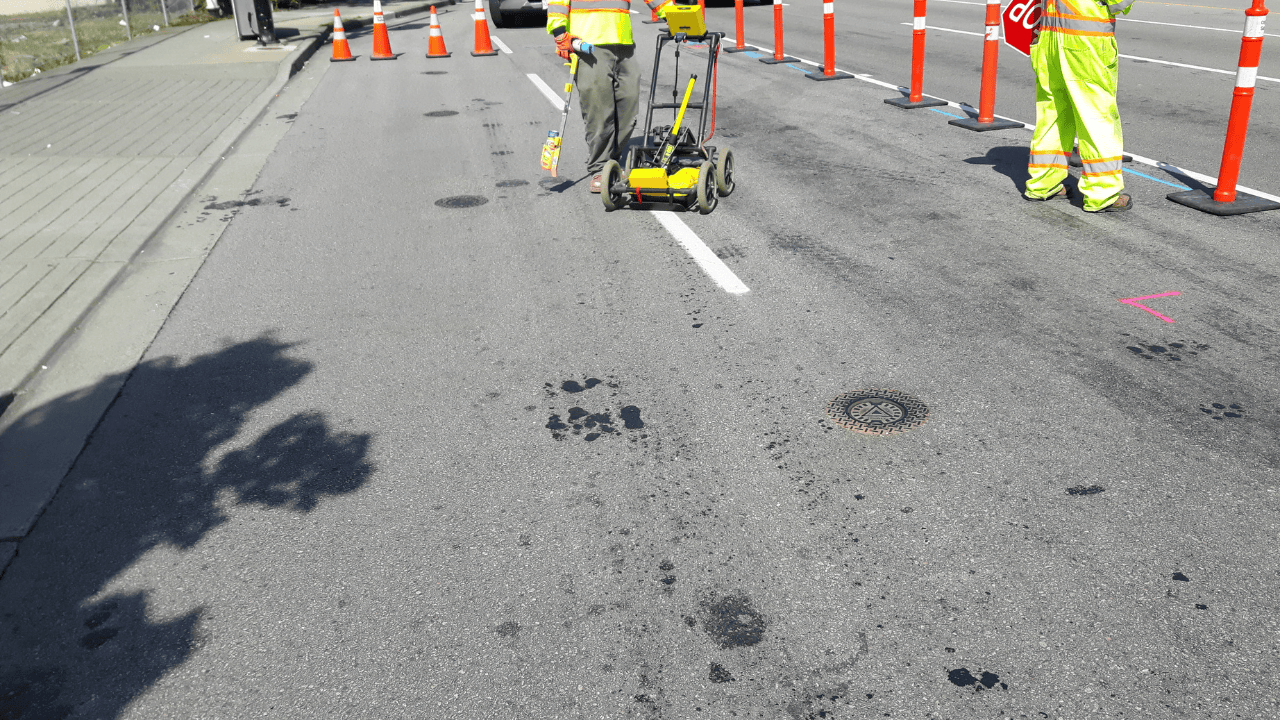
Vacuum Excavation for Telecommunications Infrastructure

exposing underground power lines

Telecommunications infrastructure projects run through congested underground corridors where fiber-optic cables, copper telephone lines, electrical service, water mains, and legacy utilities overlap. Fiber cuts disrupt service for businesses, emergency responders, and residents. Visual confirmation before trenching or boring protects that infrastructure and keeps broadband expansion and network construction on schedule.

Vacuum excavation exposes buried utilities using high-power suction rather than mechanical digging. The method confirms exact utility depth, material, size, and direction at critical points before excavation or boring begins. Below, you will find how the process works, where it fits in broadband builds, which safety and documentation standards apply, and how verified utility data reaches the crews who need it.

Key Takeaways

  • Vacuum excavation for telecommunications infrastructure gives visual confirmation of buried utilities at fiber crossing and tie-in points
  • GPR and electromagnetic locating identify probable utility paths while potholing verifies exact depth, size, material, and direction
  • The BEAD program represents $42.45 billion in federal broadband infrastructure funding that increases subsurface verification needs
  • OSHA identifies cave-ins as the greatest trenching and excavation risk requiring protective planning
  • Documented verified utility information helps contractors and telecom teams reduce delays and rework

Vacuum Excavation for Telecommunications Infrastructure Works Through Controlled Suction

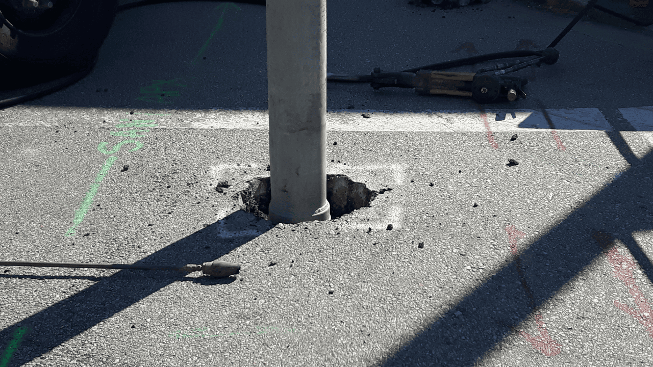
Vacuum excavation uses high-power suction to remove loosened soil during site investigation and utility verification. Material travels through an air vacuum hose into an onboard spoil tank for disposal or backfilling. The method exposes utilities at the exact points where fiber-optic trenching or conduit installation crosses existing lines.

The process delivers positive visual identification rather than relying on electromagnetic detection or ground-penetrating radar alone. Technicians confirm the location and condition of fiber-optic cables, telephone conduits, and nearby utilities before trenching or boring proceeds.

Vacuum Excavation Differs from Mechanical Digging in Force and Precision

Vacuum excavation reaches areas where machinery cannot operate safely without damaging infrastructure. It produces less surface damage and allows cleaner restoration than mechanical excavation. Reduced manual handling makes it faster and safer than hand digging for underground utility locating in the telecoms industry.

Crews in active telecommunications corridors face less debris and disruption. Controlled suction prevents the accidental contact that mechanical tools cause when they sever fiber-optic cable.

Key Components of Vacuum Excavation Systems

Vacuum excavation systems pair powerful suction equipment with debris collection tanks and specialized extraction hoses. Operators adjust suction intensity to work safely around sensitive telecommunications infrastructure, and portable units mobilize quickly for confined sites or emergency fiber repair.

System Component Function on a Telecom Site
Suction unit Lifts loosened soil away without mechanical force near fiber lines
Air or water lance Breaks up compacted soil ahead of the suction hose
Extraction hose Directs suction into narrow potholing points between utilities
Onboard spoil tank Holds removed material for backfill or offsite disposal
Operator controls Adjust suction intensity around conduit, cable, and coatings

Vacuum Excavation Enables Precise Utility Potholing

Utility potholing uses high-power vacuum suction to excavate during site investigation and verification. Built-up areas are heavily congested with existing utilities, which makes traditional excavation difficult. Vacuum excavation provides precise exposure where fiber-optic cables cross gas mains, electric service, or water lines.

Potholing confirms what electromagnetic sensors or GPR first detected. Technicians record actual depth, material type, size, and directional routing at critical junctions before network construction proceeds.

Vacuum Excavation for Telecommunications Infrastructure Verifies What Records Cannot Confirm

As-built records are often incomplete or outdated in areas with decades of development. Public locating services may not cover privately owned site utilities or supply the depth detail a project needs. Verification gives construction teams confirmed field conditions instead of estimated positions.

Fiber-optic networks depend on continuous connectivity that a single strike disrupts instantly. Documented utility positions help project managers choose trenching routes and coordinate multiple contractors in congested corridors.

Utilities Commonly Found in Telecom Infrastructure Corridors

Telecom projects involve fiber-optic cables, copper telephone lines, conduits, handholes, and vaults inside dedicated communication corridors, and they routinely cross gas, electric, water, sewer, drainage, and abandoned lines in shared ones. Older urban areas add legacy cable and unrecorded installations.

Utility Present in the Corridor Why It Complicates Fiber Work
Fiber-optic cable and conduit Shallow, closely spaced, and easily severed by mechanical tools
Copper telephone lines Legacy urban routes still carrying voice and alarm circuits
Handholes and vaults Access points where many lines converge in one dense zone
Electric power lines Often parallel telecom routes serving the same neighborhoods
Gas mains and services Crossings that raise fire and evacuation risk if struck
Water and sewer lines Occupy depth ranges similar to fiber-optic conduit
Abandoned or unrecorded lines Absent from records and discovered only in the field

GPR and Electromagnetic Locating Support Telecom Utility Detection

Electromagnetic sensors and GPR penetrate the surface non-invasively to 13 feet or more. Professional equipment reaches up to 97 percent accuracy with depth readings that identify probable utility positions. GPR and EMI technology for locating underground conduits detect metallic and non-metallic services, including polyethylene pipe and fiber-optic cable.

Method What It Identifies Limitation
Electromagnetic locating Metallic and traceable lines with depth estimates Needs a conductive path or accessible tracer wire
Ground penetrating radar Metallic and non-metallic lines, including PVC and fiber Accuracy shifts with soil type, moisture, and congestion
Vacuum excavation potholing Exact depth, size, material, and direction Verifies selected points rather than the full corridor

GPR alone cannot guarantee finding every buried service in every soil condition, so the three methods work in sequence rather than in isolation.

Visual Confirmation Through Vacuum Excavation Removes Remaining Doubt

Detection equipment identifies probable utility locations but cannot confirm exact depth, material condition, or precise positioning. Fiber-optic cables often deviate from expected routes after field adjustments or repairs, and visual exposure reveals where they actually run.

Public locating may miss private telecommunications infrastructure on commercial campuses and industrial sites. Vacuum excavation exposes privately owned fiber runs and on-site networks that public notifications do not cover.

Broadband Expansion Increases Demand for Subsurface Verification

Federal broadband funding is pushing fiber-optic deployment into unserved and underserved communities. New construction in areas with incomplete utility documentation raises verification requirements, and project managers need confirmed positions to plan safe trenching routes.

Rural broadband work often encounters aging records and unmapped private infrastructure along proposed fiber routes. Potholing at strategic points confirms subsurface conditions before crews commit to extended trenching, which reduces change orders.

The NTIA BEAD Program Drives Telecom Infrastructure Growth

BEAD is a $42.45 billion federal grant program to connect every American to high-speed internet through infrastructure partnerships. Funds deploy or upgrade service in unserved and underserved areas, and state broadband offices allocate them to local providers.

Grant-funded projects carry deployment schedules, which makes strike prevention essential. Subsurface verification protects those timelines by keeping utility surprises off the critical path.

Broadband Availability Data Informs Excavation Planning

The FCC National Broadband Map records the internet services available at individual locations and identifies the gaps that funding programs target. Those gaps show where new fiber routes will cross existing utility corridors.

Areas with inadequate service often hold aging telecommunications infrastructure with poor documentation. Planning teams use availability data to anticipate where verification effort should concentrate.

Risks of Building Without Accurate Subsurface Verification

Utility strikes cause immediate fiber cuts and service disruptions that halt progress and trigger emergency repair costs. Ten utility strikes that can be prevented include fiber-optic cable damage, gas line hits, and electric service interruptions.

Service disruption affects businesses, residential customers, emergency services, and community anchor institutions. Rework and restoration costs consume the budget that grant-funded programs allocate to new construction.

Safety Considerations and Risk Mitigations in Telecom Excavation

OSHA identifies cave-ins as the greatest risk in trenching and requires protective systems before workers enter. Employers must provide a safe means of egress in trenches four feet deep or more, and a competent person must inspect conditions daily.

Standing water and atmospheric hazards require evaluation before excavation work proceeds. Twelve safety practices during utility location cover notifications, equipment inspection, hazard assessment, and coordination protocols.

OSHA Identifies Cave-Ins as the Greatest Trenching Risk

OSHA identifies cave-ins as the greatest threat to workers in trenching operations. Collapses bury crews under thousands of pounds of soil in seconds, which leaves no time to react.

Employers must keep spoil and materials back from trench edges so added loading does not trigger a collapse. Sloping, shoring, or shielding is selected by soil type and depth.

Vacuum Excavation Supports Safer Telecom Utility Exposure

Smaller openings limit the extent of open trench and the time workers spend beside it. Less debris and less manual digging reduce both cave-in exposure and contact with live utilities.

Visual identification lets crews locate utilities accurately before mechanical equipment arrives. Confirmed positions support clearance decisions during boring and trenching in tight corridors.

Compliance Procedures for Telecom Excavation Work

OSHA requires employers to slope, shore, or shield trench walls based on soil type and depth. A competent person inspects excavations daily and after rainfall, and stops work when conditions change.

Crews should not enter a trench until inspection is complete and protective systems are in place. Daily briefings and documented verification keep telecom excavation aligned with these requirements.

Vacuum Excavation Prevents Utility Strikes and Project Disruptions

Visual confirmation removes uncertainty about utility positions at crossing points before equipment arrives. Crews adjust routes, depths, and boring paths while changes are still inexpensive.

Damage prevention protects project continuity by avoiding the service interruptions that trigger emergency repairs, penalties, and public attention. Verified positions keep fiber crews productive instead of idle.

Consequences of Utility Strikes in Telecom Projects

Gas line strikes, electric cable contact, and trench collapse injure crews and can kill. Repair costs, regulatory penalties, and liability claims follow, and outages reach customers far beyond the job site.

Outages damage contractor and operator reputations. Delays extend schedules and consume contingency budgets set aside for other work.

Damage Prevention Reporting Supports Safer Excavation Practices

Common Ground Alliance DIRT resources publish damage prevention data and practice guidance. Root cause analysis shows where notification, locating, and excavation practices break down across reported incidents.

Industry data helps contractors compare their own performance against reported patterns and target the steps that prevent repeat damage.

Practices That Reduce Uncertainty Before Digging

Request utility locates and review the as-built documentation before planning fiber-optic excavation. Mark positions from electromagnetic detection and GPR scanning to identify crossings that need confirmation. An excavation checklist for safe and successful projects covers notification, equipment inspection, and verification steps.

Choose potholing points at utility crossings and wherever documentation conflicts. Expose those utilities before committing to extended trenching, then share verified information with every stakeholder on the project.

Documentation and Utility Mapping Integrate Into Telecom Excavation

Field verification generates accurate position data that updates outdated infrastructure records. Technicians document depth, material, size, and routing at each potholing location. Three benefits of utility mapping include reduced planning downtime, lower excavation risk, and confidence before construction begins.

Documentation supports coordination among design engineers, contractors, facility managers, and network operators. Subsurface utility mapping and AutoCAD deliverables turn field findings into records that prevent conflicts during later construction or expansion.

Utility Information Captured During Vacuum Excavation

Technicians record a consistent set of attributes at every utility exposed during potholing, which gives designers and field crews a common reference.

Attribute Recorded What It Confirms
Depth Vertical clearance relative to the proposed fiber-optic route
Size and material Whether the line is fiber conduit, copper cable, or steel gas pipe
Direction How the utility trends beyond the exposed point
Condition Coating, corrosion, and evidence of prior repair at the exposure
Photographs and field notes Visual record of the utility and surrounding soil

Utility Maps Help Telecom Teams Coordinate

Mapping deliverables arrive in PDF, CAD, and KML formats compatible with project management platforms. Shared files keep design engineers, boring contractors, and telecom installers working from the same subsurface data.

Digital maps track progress and flag upcoming work areas that need further verification. Updated records support facility managers and network operators during future maintenance.

Standards That Guide Accurate Utility Documentation

ASCE C-A 38-02 provides guidelines for subsurface utility engineering and documentation accuracy. Quality level classifications define the certainty behind each utility position, from records research through visual confirmation.

Consistent practice lets organizations share data in compatible formats and supports integration with municipal GIS and regional coordination databases.

Step-by-Step Process for Excavation in Telecommunications Infrastructure

Verification begins with locate requests and a review of available infrastructure documentation. Surface markings from electromagnetic detection and GPR scanning identify probable positions, and strategic potholing points focus effort on high-risk crossings.

Vacuum excavation at those points confirms conditions before mechanical equipment begins trenching. Documented results become the reference every crew works from through installation.

Utility Locates and Markings Performed Before Excavation

Locate requests submitted to regional notification centers trigger marking of public utilities by their owners. Electromagnetic equipment traces metallic lines such as copper telephone cable and steel gas pipe, while GPR scanning finds fiber-optic cable and PVC water service.

Color-coded paint or flags indicate probable positions under American Public Works Association standards. Private utility detection then covers on-site telecommunications infrastructure that public locates skip.

When and Where Vacuum Excavation Applies on a Telecom Site

Choose potholing points where fiber optic trenching must pass over or under existing infrastructure. Service connection points where conduits tie into buildings need clearance confirmation, and areas with conflicting documentation need field evidence before a route is fixed.

Verification carries the most value at decision points where route adjustments remain feasible. How vacuum excavation minimizes traffic disruption during roadworks shows the same benefits in active telecommunications corridors.

Excavation Data Sharing With Construction and Telecom Teams

Field documentation reaches project teams through digital mapping deliverables, photographic records, and written position reports. Construction coordinators fold verified data into work plans and crew safety briefings.

Telecom installers use confirmed positions to refine cable routing and set protection protocols. Shared records give every stakeholder the same understanding of subsurface conditions.

Vacuum Excavation’s Role in Ensuring Safe, Reliable Telecommunications Infrastructure

Vacuum excavation protects buried fiber-optic cables, telephone conduits, and adjacent utilities during network construction and broadband expansion. Electromagnetic detection and GPR identify probable positions, and potholing verifies exact depth, material, and routing at critical points. Documented results reduce strike risk and hold project schedules.

Util-Locate has served telecommunications projects across Southern California and Arizona since 2001, completing roughly 11,187 locates each year at a 97 percent accuracy rate. Certified technicians deliver utility detection, strategic potholing, and ASCE-compliant documentation for safe network construction.

Schedule Vacuum Excavation With Util-Locate

Telecom crews cannot afford to guess at what sits under a fiber route. Util-Locate exposes and documents buried utilities before your trenching or boring begins, across all Southern California and Arizona counties, with 24/7 emergency response when a line is already at risk. Call 1-888-885-6228 or request a quote to schedule a site visit with a certified technician.

Frequently Asked Questions

Q1. How Deep Can Vacuum Excavation Confirm a Telecom Utility?

Vacuum excavation exposes utilities at the depths where fiber-optic conduit and shared corridor lines usually sit, most often within the first several feet of soil. Electromagnetic sensors and GPR reach 13 feet or more to identify probable positions, and potholing then verifies the specific point. Soil type, moisture, and utility congestion affect how quickly an exposure is completed. Routes that cross several utilities normally need more than one exposure.

Q2. Does 811 Cover Private Telecom Infrastructure?

No. Regional 811 notification centers arrange marking for publicly owned utilities up to the meter or the right-of-way boundary. Fiber runs, conduits, and communication networks on commercial campuses, industrial sites, and institutional properties usually fall outside that coverage. Private utility locating and vacuum excavation close the gap by finding and confirming those lines before excavation starts.

Q3. How Does Vacuum Excavation Protect Fiber During Horizontal Directional Drilling?

Directional drilling follows a planned path underground, so an inaccurate utility position stays invisible until the bore head reaches it. Potholing at each planned crossing exposes the conflicting utility and confirms clearance before the bore begins. Crews then adjust entry angles, depths, or alignments using confirmed field data. The exposed points also give the drill operator physical reference marks during the run.

Q4. How Long Do Utility Markings and Verified Positions Stay Valid?

Surface markings fade with weather, traffic, and construction activity, and most notification centers set a validity window measured in weeks. Verified potholing data holds its value longer because it records depth, size, and material rather than a painted line. Positions still change when new utilities are installed or existing lines are repaired or rerouted. Re-verification is worth scheduling when excavation is delayed or a route changes.

Q5. What Should a Telecom Contractor Expect During a Vacuum Excavation Visit?

A crew arrives with site plans, prior locate records, and results from any electromagnetic or GPR scanning already completed. Technicians expose the target utility with suction, hold the spoil in an onboard tank, and record depth, material, size, and direction on-site. Restoration follows once the exposure is documented and photographed. Util-Locate delivers the results as PDF, CAD, and KML files that project teams can use immediately.

Vacuum Excavation Services for Oil and Gas Facilities

utility locating

Oil and gas facilities often combine active pipelines, legacy infrastructure, utility corridors, electrical systems, communications networks, and tight maintenance windows. Confirming what exists underground matters before crews break ground because unplanned utility strikes can trigger safety incidents, service disruptions, environmental exposure, emergency response costs, and project delays. Professional vacuum excavation addresses these risks by physically exposing buried infrastructure without mechanical force.

Vacuum excavation supports safe exposure, verification, documentation, and handoff for energy, utility, and renewable-site work. This non‑destructive digging method removes soil using high-power suction rather than mechanical blades or backhoe buckets, reducing the chance of damaging buried gas lines, electrical conduits, water mains, sewer systems, fiber-optic cables, and unknown or abandoned infrastructure during facility upgrades, pipeline repairs, valve installations, and trenching operations.


Key Takeaways

  • Vacuum excavation verifies the physical location, depth, and material of utilities before higher-risk excavation begins
  • CGA identifies failure to verify marks by potholing as one of six primary root causes in 2023 utility damage data
  • Natural gas accounted for approximately 40% of reported facility damages in CGA 2023 DIRT data
  • PHMSA confirms excavation damage can cause deaths, injuries, property damage, and environmental damage
  • A layered method combining 811, private locating, GPR, mapping, and potholing fits congested facility conditions better than relying on one technique

What is Vacuum Excavation and How Does It Work?

Key Features of Vacuum Excavation

Vacuum excavation uses high-power suction to loosen soil or other material and remove it through an air vacuum hose. The excavated spoil and debris are stored in an onboard tank for later disposal or backfilling. This process allows operators to work around buried utilities without applying mechanical force that could rupture pipes, sever cables, or damage protective coatings.

Difference Between Vacuum Excavation and Traditional Methods

Traditional excavation methods can damage utilities, endanger workers and the public, and cause supply disruption, lost revenue, negative publicity, customer-service problems, delays, and client relationship damage. Ground-penetrating radar and electromagnetic locating help identify likely utility paths while mapping records findings. Utility potholing then exposes and visually confirms the physical utility location, depth, material, and condition.

Role of Vacuum Excavation in Utility Exposure

Vacuum excavation physically exposes utilities for confirmation rather than replacing all locating and mapping activities. It serves as the final verification step after non-invasive detection methods identify probable utility locations. This visual confirmation allows project teams to measure exact depth, assess utility condition, verify material type, and document clearance distances before authorizing mechanical excavation or directional drilling.

Why is Vacuum Excavation Important for Oil and Gas Facilities?

Risks of Excavation Damage in Oil and Gas Sites

PHMSA confirms excavation damage to pipelines can result in deaths, injuries, property damage, and environmental damage. Mechanical digging in oil and gas environments can create safety incidents, service disruption, environmental exposure, emergency response requirements, facility downtime, and repair costs that exceed initial project budgets. Unplanned utility strikes may also trigger regulatory investigations and public scrutiny.

Common Types of Buried Utilities at These Facilities

Utility investigations at oil and gas facilities may identify sewer lines, storm drains, gas distribution systems, water mains, reclaim lines, fire water systems, communications cables, electrical conduits, low-voltage circuits, abandoned infrastructure, and unknown utilities. Understanding how utility location works becomes essential when multiple systems occupy the same corridor. Gas line detection requires special attention because natural gas accounted for approximately 40% of reported damages in CGA 2023 DIRT data.

Utility Type Primary Risk if Struck
Natural gas lines Fire, explosion, evacuation, service outage
Electrical conduits Shock hazard, outages affecting critical operations
Water mains and fire water systems Flooding, pressure loss, fire suppression failure
Communications and fiber-optic cables Data loss and safety-system disruption
Sewer lines and storm drains Environmental release and cleanup costs
Abandoned or unknown infrastructure Unplanned discovery and project delay

Safety and Compliance Considerations

CGA’s 2023 DIRT Report shows the new CGA Index score was 94, a six-point decline from the 2022 baseline of 100. Six primary damage root causes accounted for 76% of incidents for the third consecutive year. These root causes include failure to notify 811, failure to maintain clearance, facility not marked due to locator error, improper excavation practice, inaccurate marks due to locator error, and excavating before verifying marks by potholing.

Metric 2023 Data Point
CGA Index score 94, down from a 2022 baseline of 100
Six primary root causes’ share of incidents 76% of incidents, third consecutive year
Natural gas share of reported damages About 40%
Telecom facilities share of reported damages Nearly half
Odds of an on-time excavation start (811 data) Roughly 50/50

How Does Vacuum Excavation Fit Into Utility Verification Workflows?

Initial Steps: Site Plans, 811 Calls, and Private Locating

Comprehensive verification begins by collecting as-builts, site plans, previous survey records, scope drawings, aerials, and area descriptions. Calling 811 initiates public utility marking for municipal infrastructure. Private utility locating addresses onsite utilities not covered by 811, such as facility-owned systems, industrial service lines, and proprietary infrastructure across oil and gas sites.

Use of Electromagnetic Locating and Ground Penetrating Radar

Electromagnetic locating and ground-penetrating radar provide non-invasive detection of buried infrastructure. GPR can detect metallic and non-metallic services including polyethylene water pipes, gas pipes, and fiber-optic cables. Preventing damage to underground utilities requires mapping findings into CAD, PDF, KML, or project documentation formats that construction teams can reference throughout the work.

When and Why to Use Vacuum Excavation for Visual Confirmation

Visual confirmation through vacuum excavation becomes necessary where depth, size, material, or conflict verification is required before mechanical excavation. Potholing confirms the exact position of utilities that electromagnetic or GPR surveys identify as probable. This step reduces uncertainty when tight clearances exist, when legacy documentation does not match field conditions, or when regulatory requirements mandate physical verification before breaking ground.

What Are Typical Use Cases for Vacuum Excavation in Energy and Utility Sites?

Pipeline Tie-Ins, Repairs, and Valve Installation

Pipeline tie-ins, repairs, valve work, and depth verification represent common applications at oil and gas facilities. Exposing existing infrastructure without mechanical contact allows welders, fitters, and inspectors to access connection points safely. Vacuum excavation also supports integrity assessments by revealing pipe condition, coating quality, and corrosion indicators before repair work begins.

Facility Upgrades and Trenching Support Near Utilities

Facility upgrades near buried utilities require trenching support where existing systems must be exposed before digging. Renewable and energy-site utility corridors often feature overlapping electrical, fiber, grounding, water, and drainage systems. Utility locating services identify probable utility paths, while potholing confirms clearance distances before contractors install new infrastructure or expand existing facilities.

Emergency Response and Legacy Documentation Updates

Emergency verification becomes necessary after a suspected strike, leak, washout, or undocumented utility discovery during excavation. Documentation updates ensure legacy plans match field conditions for future maintenance, contractor handoff, and operational planning. The role of utility locating in the utilities industry includes maintaining accurate records that support long-term facility management and reduce risk during recurring site work.

How Do Vacuum Excavation and Other Locating Methods Compare?


Method What It Does Limitation
Electromagnetic locating Traces active conductive lines from the surface Cannot detect non-metallic pipes without a tracer wire
Ground penetrating radar Detects metallic and non-metallic utilities, voids, and rebar Accuracy varies with soil type, depth, and site congestion
Mechanical excavation Removes soil quickly with powered equipment Applies direct force that can rupture pipes or sever cables
Vacuum excavation Removes soil with suction for visual confirmation Confirms utilities already probed; does not replace locating

Mechanical Excavation Vs. Vacuum Excavation

Mechanical excavation uses backhoes, excavators, or trenchers that apply direct force to soil and buried objects. Vacuum excavation removes soil with suction, eliminating mechanical contact with utilities. This difference matters when working near pressurized gas lines, high-voltage electrical conduits, or fiber-optic cables where even minor contact can cause failure or safety incidents.

GPR and Electromagnetic Locating Vs. Vacuum Excavation

GPR alone cannot guarantee finding or identifying all buried services because soil conditions, utility depth, material composition, and site congestion affect detection reliability. Nobody can honestly guarantee locating every unknown line because site history, abandoned infrastructure, soil conditions, and nearby services create variables. Electromagnetic and GPR methods identify probable utility locations, while vacuum excavation provides visual proof.

Combining Methods for Effective Damage Prevention

Combining electromagnetic locating, GPR, mapping, and potholing gives a more comprehensive answer than relying on one technique alone. No method guarantees every unknown line, but layered verification reduces risk by cross-checking findings from multiple sources. Common utility strikes that can be prevented often result from skipping verification steps or relying exclusively on incomplete site plans.

What Factors Influence Buyer Decisions for Vacuum Excavation Services?

Safety Records and Emergency Availability

Safety records and emergency availability matter when selecting vacuum excavation providers for oil and gas facilities. Excavators faced roughly 50/50 odds of being able to begin work on time based on late-locate data from 811 centers. Buyers prioritize vendors who respond quickly, work safely around active infrastructure, and provide 24/7 emergency support when unexpected subsurface conditions arise or documentation reveals discrepancies.

Equipment Suitability and Experience with Congested Sites

Equipment suitability and experience with congested sites influence vendor selection for complex energy projects. Util-Locate maintains 97% accuracy for utility lines as deep as 13 feet using calibrated equipment and trained technicians. Buyers evaluate whether providers can navigate tight clearances, work within operational facilities, and adapt to site-specific constraints without disrupting ongoing operations.

Documentation and Deliverables for Project Management

Documentation deliverables support project management, regulatory compliance, contractor coordination, and future facility maintenance. Buyers require CAD files, georeferenced maps, photographic records, and field reports that engineering teams can integrate into as-built documentation. Clear deliverables reduce handoff errors, support permit applications, and provide reference data for subsequent phases or future excavation projects.

What Are the Key Risks That Vacuum Excavation Helps Mitigate?

Utility Strikes and Their Consequences

Six primary root causes of utility damage include failure to notify 811, failure to maintain clearance, facility not marked due to locator error, improper excavation practice, inaccurate marks due to locator error, and excavating before verifying marks by potholing. Telecom facilities accounted for nearly half of reported damages in CGA 2023 data. Natural gas accounted for about 40% of reported damages, emphasizing the importance of verification at energy facilities.

Project Delays, Cost Overruns, and Reputation Damage

Utility strikes cause project delays, cost overruns, and reputation damage that extend beyond immediate repair expenses. Emergency response, regulatory reporting, service restoration, public relations, legal review, and rework consume time and budget. Clients face scrutiny from regulators, stakeholders, and the public when excavation incidents disrupt service or threaten safety, making damage prevention a strategic priority.

Environmental and Public Safety Concerns

Environmental and public safety concerns escalate when excavation damage affects oil and gas infrastructure or energy distribution systems. Pipeline ruptures can release hazardous materials, create fire or explosion risk, and require evacuation or shelter-in-place orders. Electrical strikes may cause outages affecting hospitals, water treatment plants, and emergency services, while communication failures disrupt public safety networks during critical incidents.

Ensure Safe and Verified Utility Exposure with Util-Locate!

Safe and verified utility exposure depends on selecting providers who understand the layered risks at oil and gas facilities. Combining 811 notification, private utility locating services, electromagnetic detection, ground-penetrating radar, subsurface mapping, and vacuum excavation delivers comprehensive damage prevention. This approach addresses the complexity of energy sites where legacy infrastructure, active systems, and unknown utilities coexist within congested corridors.

Util-Locate supports California and Arizona oil and gas facilities, utility projects, and renewable energy sites with precise subsurface verification services. Certified technicians use calibrated equipment to locate, map, and safely expose buried infrastructure before excavation begins. Documentation deliverables support project planning, regulatory compliance, and operational handoff for facilities requiring ongoing maintenance and future expansion.

Contact Util-Locate before breaking ground to schedule utility locating surveys that reduce strike risk and protect your project timeline. Reach the California office at (714) 492-1380, the Arizona office at (480) 535-0230, or call toll-free at (888) 885-6228 for 24/7 emergency support and service scheduling.

Frequently Asked Questions

Q1. Do vacuum excavation services confirm utility locations at oil and gas facilities?

Yes. Vacuum excavation physically exposes a utility after electromagnetic locating or ground-penetrating radar has identified its probable path. Certified technicians use high-power suction to remove soil around the line without applying mechanical force, so crews can see the exact depth, size, and material before excavation equipment moves in. This visual confirmation step is what regulators and safety programs mean when they call for verification by potholing. Skipping it is one of the six primary root causes behind reported utility damage.

Q2. How deep can vacuum excavation confirm a buried utility?

Util-Locate maintains 97% accuracy for utility lines as deep as 13 feet using calibrated equipment and trained technicians. Depth capability depends on soil conditions, utility material, and site congestion, so a site assessment usually precedes any potholing work. Facilities with layered or legacy infrastructure often need more than one exposure point to fully verify clearance. Documentation from each exposure feeds directly into project mapping and as-built records.

Q3. Is vacuum excavation safer than mechanical excavation near active pipelines?

Vacuum excavation removes soil with suction rather than the mechanical force of a backhoe or trencher, which lowers the chance of rupturing a pipe, severing a cable, or damaging a protective coating. PHMSA confirms excavation damage to pipelines can cause deaths, injuries, property damage, and environmental harm, so non-destructive methods are preferred wherever clearance is uncertain. It does not replace locating or mapping; it verifies what those methods identify. Oil and gas sites with active pipelines and legacy infrastructure typically require this extra confirmation step before mechanical digging begins.

Q4. How does vacuum excavation fit into an 811 utility locating process?

Calling 811 starts public utility marking for municipal infrastructure, but private utility locating covers facility-owned systems, industrial service lines, and proprietary infrastructure that 811 does not mark. Electromagnetic locating and ground-penetrating radar then narrow down probable utility paths across the site. Vacuum excavation is the final step in that sequence, physically exposing the utility so crews can confirm depth, material, and condition before authorizing mechanical excavation or directional drilling. Combining these layers reduces the uncertainty that any single method leaves behind.

Q5. What should a facility expect during a vacuum excavation service call?

A crew typically arrives with site plans, prior survey records, and results from any electromagnetic or GPR scans already completed. Technicians use vacuum excavation equipment to expose the target utility, store the removed spoil in an onboard tank, and document depth, material, and condition on-site. Documentation deliverables, including CAD files, georeferenced maps, and field reports, are provided for project management and future maintenance records. Util-Locate supports California and Arizona oil and gas facilities, utility projects, and renewable energy sites with this service, including 24/7 emergency response when unexpected conditions arise.

Hydro Excavation for Municipal Utility Projects

Municipal rights-of-way hold layered water, sewer, electric, gas, telecom, and fiber lines that all need protection during construction. Hydro excavation for municipal utility projects gives public works teams a way to expose those lines without service interruptions, safety incidents, or schedule slips. Pressurized water paired with vacuum recovery lets crews see depth, material, and conflicts before any blade touches soil. The method works alongside underground utility locating and ground-penetrating radar rather than replacing either one.

Below, you will find how the process works, where it fits across project phases, which municipal jobs gain the most from it, and how crews plan, protect, and document each dig. Util-Locate has performed this work across Southern California and Arizona since 2001.

Key Takeaways

  • Hydro excavation uses pressurized water and vacuum recovery to expose utilities more precisely than mechanical digging
  • FHWA research shows subsurface utility engineering returns $4.62 for every $1.00 invested across highway projects
  • PHMSA warns that pipeline markers show only general location and do not indicate precise depth or alignment
  • Visual utility confirmation reduces strike risks during water main repairs, storm drain work, and roadway reconstruction
  • OSHA excavation safety requirements remain necessary even when using non-destructive hydro excavation methods

Hydro Excavation for Municipal Utility Projects Explained

Hydro excavation is a non-destructive digging method. Pressurized water loosens soil while a vacuum system lifts the material away, so buried lines never meet the blade contact that damages them during backhoe or trenching work. Utility potholing and vacuum excavation create small access points where crews inspect pipe diameter, material type, and exact depth.

Technicians direct water into the excavation zone to break up compacted soil, then a high-power vacuum transfers the loosened material into a debris tank. Operators work within inches of live lines without mechanical impact that could crack pipes or sever cables.

Hydro Excavation Compared With Air Vacuum Excavation

Both methods use vacuum recovery. The difference is the medium that breaks up the soil, and site conditions decide which one fits. Choosing between hydro and air excavation depends on soil type, weather, and the utilities being exposed.

Factor Hydro (water) excavation Air vacuum excavation
Soil-loosening medium Pressurized water Compressed air
Strongest in Dense clay, compacted urban fill Freezing weather, sandy or loose soil
Spoil produced Wet slurry needing containment Dry soil often reusable as backfill
Speed on hard ground Faster Slower
Watch-outs Slurry handling, moisture-sensitive lines Reduced cutting power in hard-packed ground

Vacuum Methods Compared With Mechanical and Hand Digging

Vacuum excavation removes soil more precisely than a backhoe in congested corridors, because mechanical equipment cannot adjust blade depth once the operator commits to a scoop. Smaller excavation windows also limit traffic disruption, restoration work, and dust. The trade-off is throughput, since vacuum methods take longer per cubic yard in open areas with high soil volume.

Method Precision near live lines Volume rate Typical municipal use
Hydro or air vacuum excavation High, no blade contact Moderate Potholing, tie-ins, crossings
Mechanical excavation Low once the bucket commits High Bulk trenching away from known lines
Hand digging High but slow Low Final inches around an exposed line

Core Components of a Hydro Excavation Setup

Water pressure adjusts to soil density and to the sensitivity of nearby infrastructure such as fiber optic cable, and operators reduce pressure in the final inches above a utility surface. A vacuum system moves loosened material into a debris tank mounted on the truck, which keeps spoil out of storm drains. Tank capacity sets how long a crew works before hauling material to a disposal site.

Hydro Excavation for Municipal Utility Projects Reduces Strike Risk and Downtime

Municipal work often lands where several underground systems overlap inside a narrow right-of-way. Water mains cross beneath sewer lines, and fiber shares trenches with electric conduit. Hydro excavation supplies the visual proof that as-built drawings and locating alone cannot guarantee.

Private underground utility locating services identify probable utility paths, but only physical exposure confirms exact depth, material condition, and spatial conflicts. That verification cuts change orders and protects the service continuity public works directors answer for.

Visual Confirmation Cuts Utility Strike and Disruption Risk

Crews confirm a line’s presence, alignment, size, and condition instead of trusting decades-old drawings. Field verification matters most at complex intersections where several utility owners share corridor space, since exposing one line often reveals a conflict that never appeared on the construction plans. Accurate subsurface data prevents damage that would interrupt water service, sever fiber, or trigger a gas release.

Safety Gains Over Mechanical Excavation

Mechanical excavation near hidden utilities creates risk because operators have no visual information once soil removal starts. Hydro excavation lowers utility-damage risk during exposure, and workers face fewer unknowns when infrastructure is uncovered before hand tools or equipment continue. It does not remove trenching duties, since OSHA still requires cave-in protection, safe access and exit points, and regular trench inspection.

Schedule and Budget Control From Early Verification

An FHWA and Purdue University study found subsurface utility engineering returned $4.62 for every $1.00 spent across 71 projects in Virginia, North Carolina, Texas, and Ohio, representing construction value above $1 billion. Savings came from fewer utility relocations, fewer change orders, and conflicts caught during design rather than construction.

Verified depth and material data let engineers refine trench alignment, adjust pole placement, and sequence relocations before mobilization. Early field verification prevents rework, repair costs, and the service interruptions that damage a project’s reputation.

Project Stages Where Hydro Excavation Delivers Value

The method fits four phases: pre-design investigation, pre-construction verification, active construction support, and emergency response. Timing changes the payoff. Early verification reduces redesign cost, while late-stage potholing prevents damage during active trenching.

Public works teams fold the method into a workflow that starts with utility locating and record review, then confirm critical conflicts before contracts close.

Project stage What crews confirm Why it pays off
Pre-design investigation Depth and horizontal alignment at design control points Design avoids conflicts instead of relocating them later
Pre-construction verification Crossings, tie-ins, and clearances before mobilization Contracts and sequencing reflect real field conditions
Active construction Utility positions ahead of trenching and boring Trades share the corridor without strikes
Emergency response The damaged section and adjacent lines Repairs proceed without causing a second failure

Pre-Design and Site Investigation Potholing

Potholing uses high-power vacuum suction to excavate soil during site investigation. Subsurface utility engineering, promoted by FHWA since 1987, applies locating and record review first to narrow probable positions, then confirms them physically. Pre-design potholing helps engineers verify depth and alignment at the points that drive design, such as intersection improvements, storm drain installations, and roadway widening.

Potholing and Daylighting Before Construction

Daylighting exposes a buried utility for visual confirmation of location, depth, and material condition. Potholing is the controlled excavation that verifies size, depth, and material before work approaches sensitive infrastructure. Municipal teams prioritize it at utility crossings, service tie-ins, alignment bends, and corridors with conflicting records. Calling Arizona 811 before digging covers public utilities, but it does not close private facility gaps or confirm precise depth.

Active Construction and Emergency Repair Support

Exposed utility information guides sequencing when several trades need the same trench corridor. Water main repair benefits from vacuum methods that expose the damaged section without disturbing adjacent sewer or gas lines. Storm drain replacement pairs hydro excavation with CCTV drain surveys to verify pipe condition and connection points. Emergency breaks need fast access, and vacuum methods deliver it while limiting collateral damage.

Municipal Use Cases That Benefit From Hydro Excavation

Water, sewer, storm drainage, roadway, and energy systems share congested underground space. Each utility type presents a different exposure challenge based on pipe material, operating pressure, and proximity to neighboring lines, so crews adjust water pressure and vacuum settings to match.

Knowing which project types gain the most from vacuum excavation helps a municipality direct its investigation budget toward high-risk work.

Municipal work Lines usually in play What exposure confirms
Water and sewer main repair Pressurized water, gravity sewer, gas, electric Pipe material, depth, and joint condition before cutting
Storm drain and culvert work Storm lines, laterals, roadway drainage Connection points and structural condition
Roadway and streetscape upgrades Water services, drainage structures, telecom Clearances before surface removal and grading
Signal, lighting, and fiber conduit Electric, telecom, legacy conduit Safe trench paths inside occupied corridors
Renewable energy and EV infrastructure Electrical distribution, undocumented site utilities Tie-in points and foundation clearances

Water, Sewer, and Storm Drain Projects

Utility locating before sewer line repairs identifies probable pipe positions, and hydro excavation confirms them before cutting or replacement starts. Storm drain, culvert, and inspected pipeline work combines video inspection with physical exposure to verify connection points and structural condition. Water main breaks demand rapid access while gas, electric, and communication lines in the same trench stay intact.

Roadway and Infrastructure Upgrades

Reconstruction, sidewalk replacement, curb installation, and streetscape work all require exposing utilities before surface removal and grading. Relocations often move water services, drainage structures, and communication lines to make room for wider lanes. Vacuum excavation minimizes traffic disruption during roadworks by shrinking excavation footprints and restoration requirements.

Renewable Energy and Utility Relocation Projects

Solar field trenching runs electrical infrastructure across large sites where underground utilities may be poorly documented. Battery storage foundations need subsurface verification before excavation for structural supports. Interconnections require precise exposure of existing electrical infrastructure before tapping distribution systems, and EV charging installations place new conduit in parking areas and street corridors that already carry utilities.

Planning Decisions Behind Municipal Hydro Excavation

Planning starts with utility locating, record review, and risk assessment. Not every point on a project needs physical exposure, but high-consequence locations do. A clear decision framework helps directors spend investigation budgets where a strike would halt construction or cut service to residents.

Site conditions also govern timing. Traffic control, spoil handling, environmental permits, and utility owner notifications must line up before vacuum excavation starts inside a public right-of-way.

Integrating Utility Locating, GPR, and Hydro Excavation

Electromagnetic locating reaches 97% accuracy up to 13 feet deep in favorable conditions, without disturbing pavement or soil. Ground-penetrating radar adds coverage of non-metallic utilities and maps subsurface layers that affect excavation planning. Teams review locating data, as-built drawings, and GPR results together, then select pothole locations where visual confirmation returns the most value.

Conditions That Put Hydro Excavation First

Congested utility corridors, high-pressure gas lines, primary electrical feeders, and fiber backbones justify non-destructive methods on their own. So do outdated as-built records, conflicting utility owner data, and suspected abandoned infrastructure. Trenchless installations still need potholing to verify clearances for horizontal boring, and emergency repairs need speed and utility protection at the same time.

Site Preparation and Safety Measures

Crews coordinate traffic control, spoil handling, environmental controls, site access, lane closures, and restoration before work begins, and contacting the local One-Call center remains mandatory. OSHA requires trench inspection before each shift and safe entry and exit for any excavation deeper than four feet. Keeping spoil and equipment back from trench edges, managing standing water, and checking atmospheric hazards belong on every excavation checklist.

Documentation and Compliance Gains From Field Verification

Field-verified positions produce better project records than design assumptions or aging as-built drawings. Agencies use exposed utility data to update master utility maps, adjust design plans, and build documentation that later projects depend on. Utility mapping services convert field observations into CAD drawings, GIS data, and KML files that engineers open during planning.

Documented verification also eases compliance with federal, state, and local requirements, and projects using federal highway funds or grant support often require subsurface utility engineering. Sound records reduce legal exposure by showing that reasonable investigation preceded excavation.

Utility Mapping and CAD Deliverables

Field crews record depth, pipe material, diameter, condition, and horizontal position relative to survey benchmarks or street centerlines. Those observations become CAD files, KML formats, and record drawings that overlay verified positions onto base maps showing streets, property lines, and surface features. Digital records build institutional knowledge instead of scattered paper as-builts.

Visual Confirmation Improves Records and Conflict Resolution

Exposure resolves disagreements between as-builts filed by different utility owners or construction eras, and it reveals materials, depths, and alignments that drifted from design intent over decades. Photographic documentation supports design adjustments, change order negotiation, and dispute resolution. That evidence moves a project from change-driven delay toward predictable execution.

CCTV Pipe Inspection for Sewer and Drainage Verification

CCTV pipe inspection verifies internal condition, joint alignment, and structural integrity before sewer or storm drain replacement, flagging root intrusion, collapse, offset joints, and blockages. Paired with external exposure at key points, video gives a complete condition assessment, helps prioritize segments inside capital improvement programs, and documents conditions before and after construction.

Common Municipal Excavation Risks and Their Controls

Municipal excavation carries utility strikes, trench collapses, service interruptions, traffic disruption, and environmental releases. OSHA identifies cave-ins as the greatest threat to worker life in trenching and excavation work, and PHMSA treats accidental excavation damage as one of the greatest challenges to safe pipeline operation.

Damage reaches gas, electric, water, sewer, telecom, and private facilities, and the resulting interruptions create public complaints, emergency response costs, and political accountability.

Risk Consequence Control
Utility strike Outages, injuries, emergency repair costs Locate first, then expose with vacuum methods before trenching
Trench cave-in Primary worker fatality risk in trenching Shoring or sloping, spoil setback, inspection each shift
Service interruption Public complaints, business and hospital impact Verified depth and alignment before cutting or tapping
Traffic disruption Extended lane closures and restoration Smaller excavation footprints and staged closures
Environmental release Slurry or spoil entering storm drains Contained debris tanks and permitted disposal

Utility Strike and Public Impact Risks

Strike prevention starts by removing blade contact between equipment and buried infrastructure. Hydro excavation lifts soil without the cutting forces that sever cable, crack pipe, or puncture pressurized lines, so gas, electric, water, sewer, telecom, and fiber incidents all decline. Disruption from a strike usually exceeds the original excavation impact, since emergency repair adds closures and restoration work. Smaller excavation footprints shorten that exposure and speed project completion.

Remaining Safety and Environmental Risks

OSHA trenching controls apply regardless of the method used to expose a utility. Safe access and egress, spoil placement away from trench edges, standing water management, and cave-in protection stay in force. Standing water creates drowning hazards and weakens soil near trench walls, and ladders or ramps must let workers exit quickly. Excavation risk management remains a duty separate from utility protection.

Old Records and Unknown Utilities

Pipeline markers show general location or right-of-way only, not precise position or depth of burial. The 811 One-Call system does not cover private installations on commercial properties, campuses, or industrial sites. Municipal corridors mix public infrastructure, private facilities, abandoned lines, and construction from several eras, and old drawings often record design intent rather than what crews actually built.

Hydro Excavation’s Role in Safer Municipal Utility Delivery

Municipal infrastructure work balances construction pace against protection of the lines communities depend on. Hydro excavation turns subsurface uncertainty into confirmed field data before equipment mobilizes.

The FHWA cost-benefit research shows that early utility investigation protects budget and schedule against mid-construction surprises. Agencies that pair hydro excavation with utility locating, ground-penetrating radar, and mapping build lasting knowledge of what sits under their streets, which lowers service interruptions and supports compliance across water, sewer, roadway, and energy programs.

Schedule Hydro Excavation With Util-Locate

Util-Locate has supported municipal utility projects across Southern California and Arizona since 2001, combining utility locating, ground-penetrating radar, hydro excavation, CCTV pipe inspection, and ASCE-referenced mapping. Certified technicians locate buried lines up to 13 feet deep with 97% accuracy and deliver findings in PDF, CAD, and KML formats your engineers can use right away.

Call (888) 885-6228 to walk through your corridor with a specialist, or request a quote and we will scope the potholing plan around your schedule. 24/7 emergency service is available when a break cannot wait for business hours.

Frequently Asked Questions

Q1. How much does hydro excavation cost for a municipal project?

Pricing depends on the number of potholes, target depth, soil conditions, surface type, traffic control, permits, and spoil disposal. Most municipal work is quoted per pothole or as a day rate covering the truck, water, and crew. Deep exposures, hard surfaces, and congested corridors raise the per-hole figure. FHWA research puts that spend in context, showing $4.62 returned for every $1.00 invested in subsurface utility engineering. A site-specific quote remains the only reliable number.

Q2. How deep can hydro excavation expose buried utilities?

Most municipal potholes reach 3 to 8 feet, which covers typical water, sewer, gas, and telecom depths. Boom and hose extensions take crews deeper when a project calls for it, though tank capacity and spoil handling become the limiting factors. Locating results set the target depth before the truck arrives, and electromagnetic sensors with GPR support reach 97% accuracy up to 13 feet in favorable ground. Exposures below roughly five feet also bring trench protection requirements into play.

Q3. Does a municipal project still need hydro excavation after calling 811?

Yes, because the two serve different purposes. The 811 One-Call system marks member-owned public utilities and is required before excavation, but it does not confirm depth, and it does not cover private lines on campuses, commercial sites, or industrial properties. PHMSA notes that pipeline markers show only general location or right-of-way. Hydro excavation supplies the physical confirmation of depth, material, and alignment that marks alone cannot give.

Q4. How long does a single hydro excavation pothole take?

A straightforward pothole usually takes 30 to 90 minutes from setup to backfill. Depth, soil density, and surface type drive that range, since coring asphalt or concrete adds time at both ends. A crew commonly completes several potholes in one shift when the locations sit close together. Traffic control, permits, and utility owner notification often shape the schedule more than the digging itself. Most surfaces are restored the same day.

Q5. What documentation do municipal teams receive after hydro excavation?

Crews record measured depth to the utility surface, pipe material, diameter, condition, and horizontal position tied to survey control or street centerline, along with site photographs. Those observations are delivered as field reports and converted into CAD drawings, KML files, and GIS-ready data. Agencies use the results to update master utility maps and adjust design plans before construction. The same records support change order discussions and dispute resolution later in the project.