
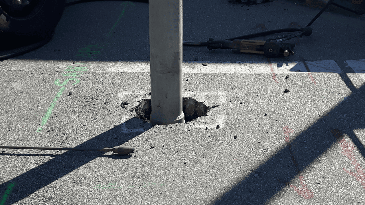
Telecommunications infrastructure projects run through congested underground corridors where fiber-optic cables, copper telephone lines, electrical service, water mains, and legacy utilities overlap. Fiber cuts disrupt service for businesses, emergency responders, and residents. Visual confirmation before trenching or boring protects that infrastructure and keeps broadband expansion and network construction on schedule.
Vacuum excavation exposes buried utilities using high-power suction rather than mechanical digging. The method confirms exact utility depth, material, size, and direction at critical points before excavation or boring begins. Below, you will find how the process works, where it fits in broadband builds, which safety and documentation standards apply, and how verified utility data reaches the crews who need it.
Key Takeaways
- Vacuum excavation for telecommunications infrastructure gives visual confirmation of buried utilities at fiber crossing and tie-in points
- GPR and electromagnetic locating identify probable utility paths while potholing verifies exact depth, size, material, and direction
- The BEAD program represents $42.45 billion in federal broadband infrastructure funding that increases subsurface verification needs
- OSHA identifies cave-ins as the greatest trenching and excavation risk requiring protective planning
- Documented verified utility information helps contractors and telecom teams reduce delays and rework
Vacuum Excavation for Telecommunications Infrastructure Works Through Controlled Suction
Vacuum excavation uses high-power suction to remove loosened soil during site investigation and utility verification. Material travels through an air vacuum hose into an onboard spoil tank for disposal or backfilling. The method exposes utilities at the exact points where fiber-optic trenching or conduit installation crosses existing lines.
The process delivers positive visual identification rather than relying on electromagnetic detection or ground-penetrating radar alone. Technicians confirm the location and condition of fiber-optic cables, telephone conduits, and nearby utilities before trenching or boring proceeds.
Vacuum Excavation Differs from Mechanical Digging in Force and Precision
Vacuum excavation reaches areas where machinery cannot operate safely without damaging infrastructure. It produces less surface damage and allows cleaner restoration than mechanical excavation. Reduced manual handling makes it faster and safer than hand digging for underground utility locating in the telecoms industry.
Crews in active telecommunications corridors face less debris and disruption. Controlled suction prevents the accidental contact that mechanical tools cause when they sever fiber-optic cable.
Key Components of Vacuum Excavation Systems
Vacuum excavation systems pair powerful suction equipment with debris collection tanks and specialized extraction hoses. Operators adjust suction intensity to work safely around sensitive telecommunications infrastructure, and portable units mobilize quickly for confined sites or emergency fiber repair.
| System Component | Function on a Telecom Site |
| Suction unit | Lifts loosened soil away without mechanical force near fiber lines |
| Air or water lance | Breaks up compacted soil ahead of the suction hose |
| Extraction hose | Directs suction into narrow potholing points between utilities |
| Onboard spoil tank | Holds removed material for backfill or offsite disposal |
| Operator controls | Adjust suction intensity around conduit, cable, and coatings |
Vacuum Excavation Enables Precise Utility Potholing
Utility potholing uses high-power vacuum suction to excavate during site investigation and verification. Built-up areas are heavily congested with existing utilities, which makes traditional excavation difficult. Vacuum excavation provides precise exposure where fiber-optic cables cross gas mains, electric service, or water lines.
Potholing confirms what electromagnetic sensors or GPR first detected. Technicians record actual depth, material type, size, and directional routing at critical junctions before network construction proceeds.
Vacuum Excavation for Telecommunications Infrastructure Verifies What Records Cannot Confirm
As-built records are often incomplete or outdated in areas with decades of development. Public locating services may not cover privately owned site utilities or supply the depth detail a project needs. Verification gives construction teams confirmed field conditions instead of estimated positions.
Fiber-optic networks depend on continuous connectivity that a single strike disrupts instantly. Documented utility positions help project managers choose trenching routes and coordinate multiple contractors in congested corridors.
Utilities Commonly Found in Telecom Infrastructure Corridors
Telecom projects involve fiber-optic cables, copper telephone lines, conduits, handholes, and vaults inside dedicated communication corridors, and they routinely cross gas, electric, water, sewer, drainage, and abandoned lines in shared ones. Older urban areas add legacy cable and unrecorded installations.
| Utility Present in the Corridor | Why It Complicates Fiber Work |
| Fiber-optic cable and conduit | Shallow, closely spaced, and easily severed by mechanical tools |
| Copper telephone lines | Legacy urban routes still carrying voice and alarm circuits |
| Handholes and vaults | Access points where many lines converge in one dense zone |
| Electric power lines | Often parallel telecom routes serving the same neighborhoods |
| Gas mains and services | Crossings that raise fire and evacuation risk if struck |
| Water and sewer lines | Occupy depth ranges similar to fiber-optic conduit |
| Abandoned or unrecorded lines | Absent from records and discovered only in the field |
GPR and Electromagnetic Locating Support Telecom Utility Detection
Electromagnetic sensors and GPR penetrate the surface non-invasively to 13 feet or more. Professional equipment reaches up to 97 percent accuracy with depth readings that identify probable utility positions. GPR and EMI technology for locating underground conduits detect metallic and non-metallic services, including polyethylene pipe and fiber-optic cable.
| Method | What It Identifies | Limitation |
| Electromagnetic locating | Metallic and traceable lines with depth estimates | Needs a conductive path or accessible tracer wire |
| Ground penetrating radar | Metallic and non-metallic lines, including PVC and fiber | Accuracy shifts with soil type, moisture, and congestion |
| Vacuum excavation potholing | Exact depth, size, material, and direction | Verifies selected points rather than the full corridor |
GPR alone cannot guarantee finding every buried service in every soil condition, so the three methods work in sequence rather than in isolation.
Visual Confirmation Through Vacuum Excavation Removes Remaining Doubt
Detection equipment identifies probable utility locations but cannot confirm exact depth, material condition, or precise positioning. Fiber-optic cables often deviate from expected routes after field adjustments or repairs, and visual exposure reveals where they actually run.
Public locating may miss private telecommunications infrastructure on commercial campuses and industrial sites. Vacuum excavation exposes privately owned fiber runs and on-site networks that public notifications do not cover.
Broadband Expansion Increases Demand for Subsurface Verification
Federal broadband funding is pushing fiber-optic deployment into unserved and underserved communities. New construction in areas with incomplete utility documentation raises verification requirements, and project managers need confirmed positions to plan safe trenching routes.
Rural broadband work often encounters aging records and unmapped private infrastructure along proposed fiber routes. Potholing at strategic points confirms subsurface conditions before crews commit to extended trenching, which reduces change orders.
The NTIA BEAD Program Drives Telecom Infrastructure Growth
BEAD is a $42.45 billion federal grant program to connect every American to high-speed internet through infrastructure partnerships. Funds deploy or upgrade service in unserved and underserved areas, and state broadband offices allocate them to local providers.
Grant-funded projects carry deployment schedules, which makes strike prevention essential. Subsurface verification protects those timelines by keeping utility surprises off the critical path.
Broadband Availability Data Informs Excavation Planning
The FCC National Broadband Map records the internet services available at individual locations and identifies the gaps that funding programs target. Those gaps show where new fiber routes will cross existing utility corridors.
Areas with inadequate service often hold aging telecommunications infrastructure with poor documentation. Planning teams use availability data to anticipate where verification effort should concentrate.
Risks of Building Without Accurate Subsurface Verification
Utility strikes cause immediate fiber cuts and service disruptions that halt progress and trigger emergency repair costs. Ten utility strikes that can be prevented include fiber-optic cable damage, gas line hits, and electric service interruptions.
Service disruption affects businesses, residential customers, emergency services, and community anchor institutions. Rework and restoration costs consume the budget that grant-funded programs allocate to new construction.
Safety Considerations and Risk Mitigations in Telecom Excavation
OSHA identifies cave-ins as the greatest risk in trenching and requires protective systems before workers enter. Employers must provide a safe means of egress in trenches four feet deep or more, and a competent person must inspect conditions daily.
Standing water and atmospheric hazards require evaluation before excavation work proceeds. Twelve safety practices during utility location cover notifications, equipment inspection, hazard assessment, and coordination protocols.
OSHA Identifies Cave-Ins as the Greatest Trenching Risk
OSHA identifies cave-ins as the greatest threat to workers in trenching operations. Collapses bury crews under thousands of pounds of soil in seconds, which leaves no time to react.
Employers must keep spoil and materials back from trench edges so added loading does not trigger a collapse. Sloping, shoring, or shielding is selected by soil type and depth.
Vacuum Excavation Supports Safer Telecom Utility Exposure
Smaller openings limit the extent of open trench and the time workers spend beside it. Less debris and less manual digging reduce both cave-in exposure and contact with live utilities.
Visual identification lets crews locate utilities accurately before mechanical equipment arrives. Confirmed positions support clearance decisions during boring and trenching in tight corridors.
Compliance Procedures for Telecom Excavation Work
OSHA requires employers to slope, shore, or shield trench walls based on soil type and depth. A competent person inspects excavations daily and after rainfall, and stops work when conditions change.
Crews should not enter a trench until inspection is complete and protective systems are in place. Daily briefings and documented verification keep telecom excavation aligned with these requirements.
Vacuum Excavation Prevents Utility Strikes and Project Disruptions
Visual confirmation removes uncertainty about utility positions at crossing points before equipment arrives. Crews adjust routes, depths, and boring paths while changes are still inexpensive.
Damage prevention protects project continuity by avoiding the service interruptions that trigger emergency repairs, penalties, and public attention. Verified positions keep fiber crews productive instead of idle.
Consequences of Utility Strikes in Telecom Projects
Gas line strikes, electric cable contact, and trench collapse injure crews and can kill. Repair costs, regulatory penalties, and liability claims follow, and outages reach customers far beyond the job site.
Outages damage contractor and operator reputations. Delays extend schedules and consume contingency budgets set aside for other work.
Damage Prevention Reporting Supports Safer Excavation Practices
Common Ground Alliance DIRT resources publish damage prevention data and practice guidance. Root cause analysis shows where notification, locating, and excavation practices break down across reported incidents.
Industry data helps contractors compare their own performance against reported patterns and target the steps that prevent repeat damage.
Practices That Reduce Uncertainty Before Digging
Request utility locates and review the as-built documentation before planning fiber-optic excavation. Mark positions from electromagnetic detection and GPR scanning to identify crossings that need confirmation. An excavation checklist for safe and successful projects covers notification, equipment inspection, and verification steps.
Choose potholing points at utility crossings and wherever documentation conflicts. Expose those utilities before committing to extended trenching, then share verified information with every stakeholder on the project.
Documentation and Utility Mapping Integrate Into Telecom Excavation
Field verification generates accurate position data that updates outdated infrastructure records. Technicians document depth, material, size, and routing at each potholing location. Three benefits of utility mapping include reduced planning downtime, lower excavation risk, and confidence before construction begins.
Documentation supports coordination among design engineers, contractors, facility managers, and network operators. Subsurface utility mapping and AutoCAD deliverables turn field findings into records that prevent conflicts during later construction or expansion.
Utility Information Captured During Vacuum Excavation
Technicians record a consistent set of attributes at every utility exposed during potholing, which gives designers and field crews a common reference.
| Attribute Recorded | What It Confirms |
| Depth | Vertical clearance relative to the proposed fiber-optic route |
| Size and material | Whether the line is fiber conduit, copper cable, or steel gas pipe |
| Direction | How the utility trends beyond the exposed point |
| Condition | Coating, corrosion, and evidence of prior repair at the exposure |
| Photographs and field notes | Visual record of the utility and surrounding soil |
Utility Maps Help Telecom Teams Coordinate
Mapping deliverables arrive in PDF, CAD, and KML formats compatible with project management platforms. Shared files keep design engineers, boring contractors, and telecom installers working from the same subsurface data.
Digital maps track progress and flag upcoming work areas that need further verification. Updated records support facility managers and network operators during future maintenance.
Standards That Guide Accurate Utility Documentation
ASCE C-A 38-02 provides guidelines for subsurface utility engineering and documentation accuracy. Quality level classifications define the certainty behind each utility position, from records research through visual confirmation.
Consistent practice lets organizations share data in compatible formats and supports integration with municipal GIS and regional coordination databases.
Step-by-Step Process for Excavation in Telecommunications Infrastructure
Verification begins with locate requests and a review of available infrastructure documentation. Surface markings from electromagnetic detection and GPR scanning identify probable positions, and strategic potholing points focus effort on high-risk crossings.
Vacuum excavation at those points confirms conditions before mechanical equipment begins trenching. Documented results become the reference every crew works from through installation.
Utility Locates and Markings Performed Before Excavation
Locate requests submitted to regional notification centers trigger marking of public utilities by their owners. Electromagnetic equipment traces metallic lines such as copper telephone cable and steel gas pipe, while GPR scanning finds fiber-optic cable and PVC water service.
Color-coded paint or flags indicate probable positions under American Public Works Association standards. Private utility detection then covers on-site telecommunications infrastructure that public locates skip.
When and Where Vacuum Excavation Applies on a Telecom Site
Choose potholing points where fiber optic trenching must pass over or under existing infrastructure. Service connection points where conduits tie into buildings need clearance confirmation, and areas with conflicting documentation need field evidence before a route is fixed.
Verification carries the most value at decision points where route adjustments remain feasible. How vacuum excavation minimizes traffic disruption during roadworks shows the same benefits in active telecommunications corridors.
Excavation Data Sharing With Construction and Telecom Teams
Field documentation reaches project teams through digital mapping deliverables, photographic records, and written position reports. Construction coordinators fold verified data into work plans and crew safety briefings.
Telecom installers use confirmed positions to refine cable routing and set protection protocols. Shared records give every stakeholder the same understanding of subsurface conditions.
Vacuum Excavation’s Role in Ensuring Safe, Reliable Telecommunications Infrastructure
Vacuum excavation protects buried fiber-optic cables, telephone conduits, and adjacent utilities during network construction and broadband expansion. Electromagnetic detection and GPR identify probable positions, and potholing verifies exact depth, material, and routing at critical points. Documented results reduce strike risk and hold project schedules.
Util-Locate has served telecommunications projects across Southern California and Arizona since 2001, completing roughly 11,187 locates each year at a 97 percent accuracy rate. Certified technicians deliver utility detection, strategic potholing, and ASCE-compliant documentation for safe network construction.
Schedule Vacuum Excavation With Util-Locate
Telecom crews cannot afford to guess at what sits under a fiber route. Util-Locate exposes and documents buried utilities before your trenching or boring begins, across all Southern California and Arizona counties, with 24/7 emergency response when a line is already at risk. Call 1-888-885-6228 or request a quote to schedule a site visit with a certified technician.
Frequently Asked Questions
Q1. How Deep Can Vacuum Excavation Confirm a Telecom Utility?
Vacuum excavation exposes utilities at the depths where fiber-optic conduit and shared corridor lines usually sit, most often within the first several feet of soil. Electromagnetic sensors and GPR reach 13 feet or more to identify probable positions, and potholing then verifies the specific point. Soil type, moisture, and utility congestion affect how quickly an exposure is completed. Routes that cross several utilities normally need more than one exposure.
Q2. Does 811 Cover Private Telecom Infrastructure?
No. Regional 811 notification centers arrange marking for publicly owned utilities up to the meter or the right-of-way boundary. Fiber runs, conduits, and communication networks on commercial campuses, industrial sites, and institutional properties usually fall outside that coverage. Private utility locating and vacuum excavation close the gap by finding and confirming those lines before excavation starts.
Q3. How Does Vacuum Excavation Protect Fiber During Horizontal Directional Drilling?
Directional drilling follows a planned path underground, so an inaccurate utility position stays invisible until the bore head reaches it. Potholing at each planned crossing exposes the conflicting utility and confirms clearance before the bore begins. Crews then adjust entry angles, depths, or alignments using confirmed field data. The exposed points also give the drill operator physical reference marks during the run.
Q4. How Long Do Utility Markings and Verified Positions Stay Valid?
Surface markings fade with weather, traffic, and construction activity, and most notification centers set a validity window measured in weeks. Verified potholing data holds its value longer because it records depth, size, and material rather than a painted line. Positions still change when new utilities are installed or existing lines are repaired or rerouted. Re-verification is worth scheduling when excavation is delayed or a route changes.
Q5. What Should a Telecom Contractor Expect During a Vacuum Excavation Visit?
A crew arrives with site plans, prior locate records, and results from any electromagnetic or GPR scanning already completed. Technicians expose the target utility with suction, hold the spoil in an onboard tank, and record depth, material, size, and direction on-site. Restoration follows once the exposure is documented and photographed. Util-Locate delivers the results as PDF, CAD, and KML files that project teams can use immediately.
