The Leading Southern California Private Utility Locating Company
Any time that a contractor, or even a homeowner, needs to dig into the ground, they run the risk of hitting utility pipes and wires. Not only can this be costly if the lines are accidentally cut or damaged, but it can also be extremely dangerous. Gas lines can explode, and electrical power lines can cause fires or electrocution. Learn more about gas line locator.
While water may not be as dangerous, a sudden release of water could cause trenches to collapse, trapping workers beneath the surface. A utility locator visits the site before work begins and locates the exact placement and depth of each type of utility on the property. With this information, workers can safely and confidently go about their business. A Private Utility Locating and Mapping Services Provider—Util-Locate provides utility locator service, using state-of-the-art technology for an accurate utility location and depth of utility lines.
WHY USE A UTILITY LOCATOR?
Any time you are preparing to dig, be certain to contact a reliable utility locator. Such services are necessary before doing any kind of digging, regardless of how small the project is. Utility lines are not always where they appear to be through the line of sight, so using the expertise of a utility locator or underground utility locator is essential. By hiring a professional, not only will you be able to conduct locating underground utilities or locating buried utilities, but also you will be capable of working on locating how deep they are buried. With a company such as Util-Locate, you have 97 percent accuracy for utility lines as deep as 13 feet. This information allows you to proceed with your project with the confidence that you will not interfere with buried utilities.
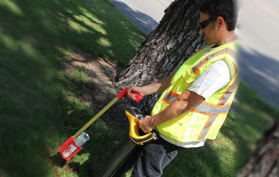
HOW DO UTILITY LOCATE TECHNICIANS DETERMINE THE LOCATION OF BURIED UTILITIES?
The utility locate technicians use a variety of electromagnetic sensors and GPR that are able to non-invasively penetrate the surface of the earth, up to a depth of 13+ feet. The signals produced by the equipment locate the pipes and wires, allowing the technicians to create a map or diagram of the location and depth of each utility present.
Although rarely needed, the utility locate technician can always return to a work site to verify any questionable findings made as construction progresses.
WHEN SHOULD YOU CONTACT UTILITY LOCATING COMPANIES?
The best time to contact a utility locating company that provides a utility locator or underground utility locator services should be before you begin to dig or design. Depending on the scope of the project, it is often essential to know exact locations and depths of utility lines during the early planning stages.
Knowing this information will allow for proper placement of structures, foundations, post support, trees, and other project items. Sometime utilities will need to be relocated. Utility locating companies will help project planners determine where those lines need to be moved to so that they will no longer pose a problem for workers and machine operators.
WHAT ARE THE BENEFITS OF UTILITY LOCATING SERVICES?
By hiring a professional utility locating service, you gain the assurance that you will be provided the most accurate information available without having to disturb existing landscaping. By using state-of-the-art electromagnetic locators and GPR equipment, utility locating companies like Util-Locate can easily find buried lines, giving exact location and depth. Older technology required technicians to make several exploratory holes in order to determine the depth of the buried lines.
EQUIPMENT USED BY UTILITY LOCATOR COMPANIES
Unlike simple handheld detectors, the electromagnetic pipe and cable locator equipment used by professional utility locator companies allows their technicians to adjust to various line and cable conditions, as well as for unexpected soil conditions. It also provides up to 97% accuracy and depth readings up to 13+ feet. Utility locator companies such as Util-Locate are making use of state-of-the-art detection equipment, providing the best utility locating services in the industry today.
")
Utility Locating Services
WHO IS THE BEST UTILITY LOCATE SERVICES IN CALIFORNIA?
If you’re looking for the best utility locate services in California, contact Util-Locate. Our professional utility locate technicians make use of state-of-the-art technology in the industry.
Call us now for your utility line detection needs or to get more information about our Utility Locating Service.
FREQUENTLY ASKED QUESTIONS
There are many types of utility locating services, but the most common is probably water line location. This involves finding and marking the location of water lines so that they can be avoided when excavating. Other types of utility locating services include gas line location, sewer line location, and electrical line location. The scope of each type of service will vary depending on the specific needs of the customer.
There are many key benefits of using utility locating services. Perhaps the most important benefit is that these services can help to prevent damage to underground utilities. When construction crews or other workers are excavating in an area, they can use utility locating services to help them avoid damaging any underground utilities. This can save the crew time and money, as well as preventing any disruptions to utility service for nearby customers.
There is no definitive answer to this question as it depends on a number of factors, including the experience and expertise of the utility locating service, the type of utility being located, the terrain and conditions of the area being searched, and the accuracy of the information provided by the client. In general, however, utility locating services are considered to be quite reliable, and many clients are satisfied with the results.
Utility locating services can be deployed very quickly, depending on the size and scope of the project. For a small project, a few days may be all that is needed. For a large project, a few weeks may be required. The key is to have a clear understanding of the project requirements and the available resources.
There is no one answer to this question as the cost of utility locating services can vary greatly depending on a number of factors. These factors can include the size and scope of the project, the geographical location, the type of utilities involved, and the experience and expertise of the utility locating company. In general, however, the cost of utility locating services is typically based on an hourly rate.
There are a variety of risks associated with using utility locating services. First and foremost, if utilities are not properly marked, excavators may unintentionally damage them while working, which can result in costly repairs, service disruptions, and even personal injury. Additionally, if underground utilities are not properly mapped, excavators may unknowingly dig through them, again causing damage and potentially injuring themselves or others.